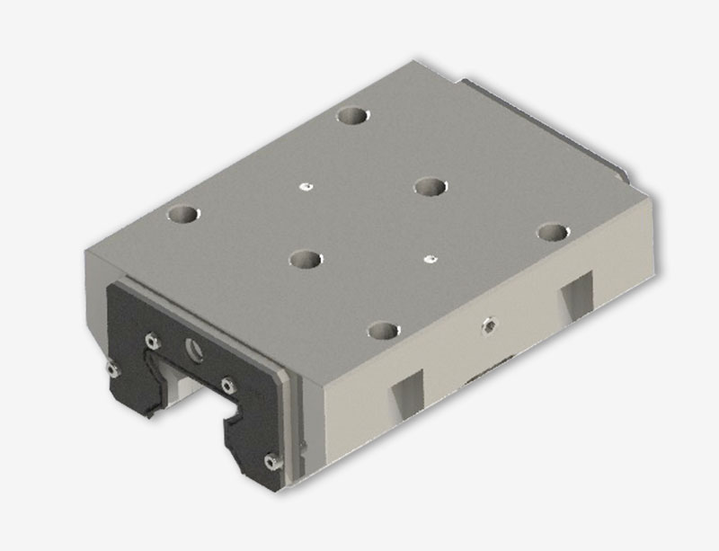
Working principle and action flow of clamp
With the advantages of high positioning accuracy, small wear and strong bearing capacity, the rolling linear guide pair has gradually replaced the traditional sliding linear guide in the machine tool industry. With the rapid development of modern machine tool manufacturing industry, higher requirements are put forward for the performance of rolling linear guide pair. As one of the optional parts of the rolling linear guide, the clamp plays an important role in further improving the rigidity of the guide, reducing the vibration of the machine tool and braking protection.
In practical use, the mounting surface of the clamp is generally coplanar with the slide of the rolling linear guide pair, which is installed on the bottom surface of the workbench together, and moves in a straight line along the direction of the guide rail together with the workbench. This equipment simulates the actual working condition, uses the screw to fix the test clamp, the rolling linear guide pair slider and the auxiliary clamp on the connecting plate, and forms the moving body together.
After the start of the test, first the auxiliary clamp and the test clamp are both in the released state, then the cylinder extends to push the moving body to move towards the spring direction, and compress the spring. When the cylinder is extended to the predetermined position, the system receives the switch signal of the front magnetic induction switch, which makes the auxiliary clamp act and clamp the guide rail, and then the cylinder retracts. Until the system receives the switch signal of the rear magnetic induction switch and performs the next action, the auxiliary clamp is released. When the auxiliary clamp is released, the moving body accelerates under the action of the spring force, and the elastic potential energy of the spring is converted into the kinetic energy of the moving body. When the moving body is separated from the spring, the moving body obtains the maximum speed. At this time, the reading value of the magnetic grid ruler is 0. At the same time, the test clamp acts and starts to brake until the moving body stops moving. The system records the reading of the magnetic grid ruler at this time as the braking distance of the test clamp. Then the system repeats the above action process until the reading value of braking distance is larger than the preset failure value, and the system stops working.


